Big Trak Obstacle Avoiding Robot
Goal:
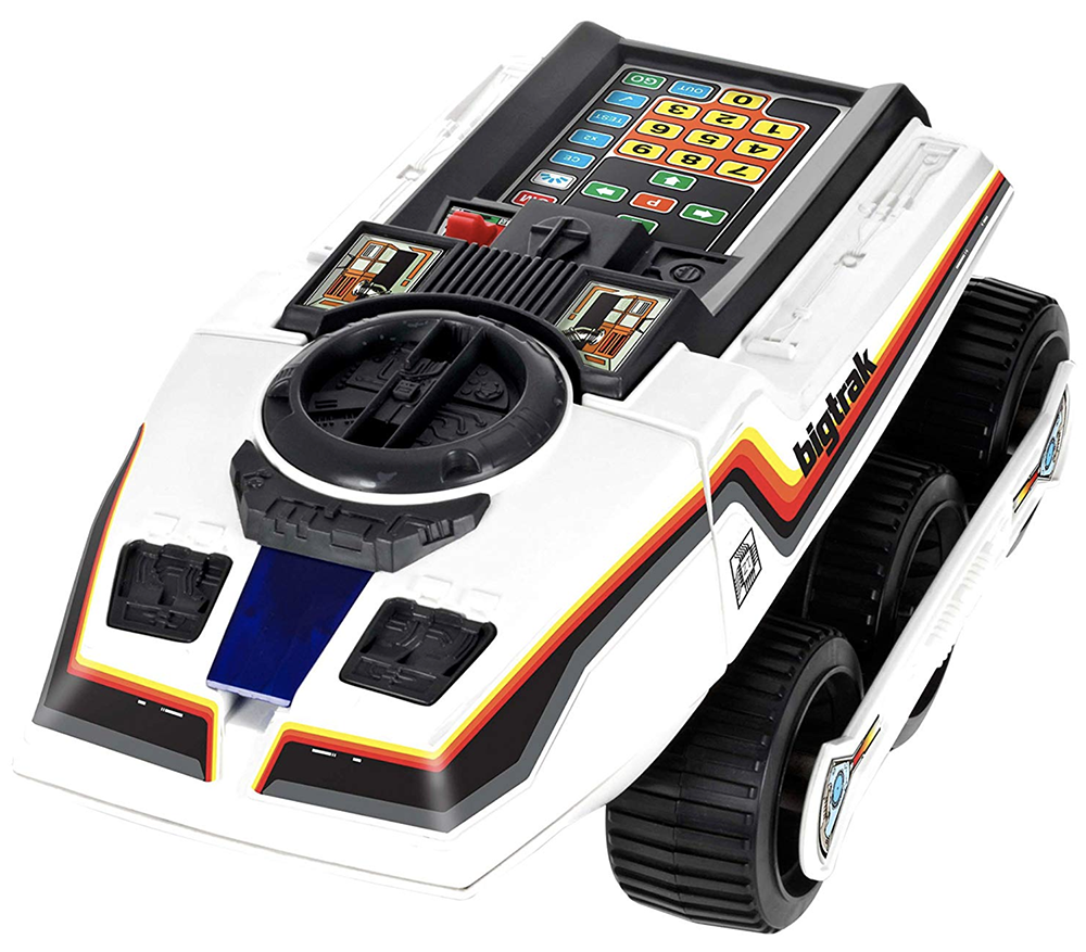
To customize the programmable toy "Big Trak" with an Arduino brain thus adding in new functionality using Arduino And creating an Obstacle Avoiding Robot.
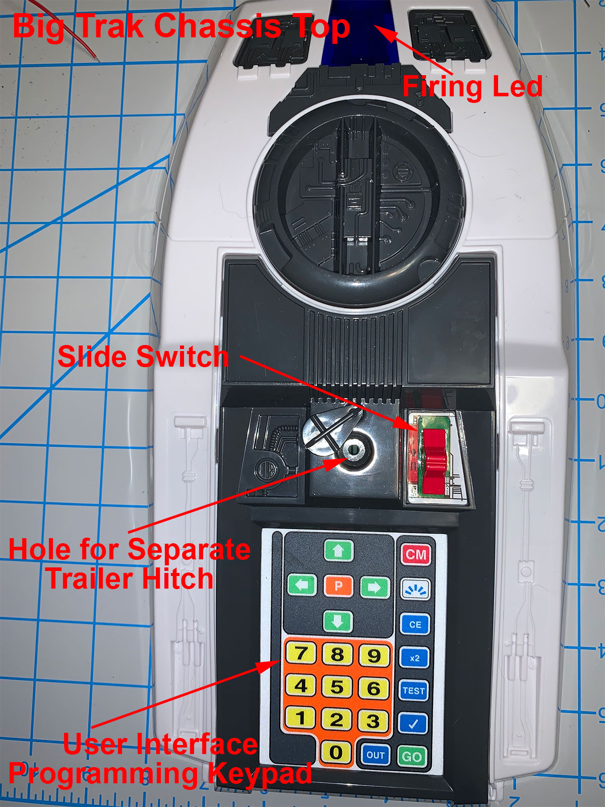
The Exterior & User Interface
I began a teardown of the Big Trak to get to the interior and learned how the User Interface / keypad was wired into the Print Control Board.
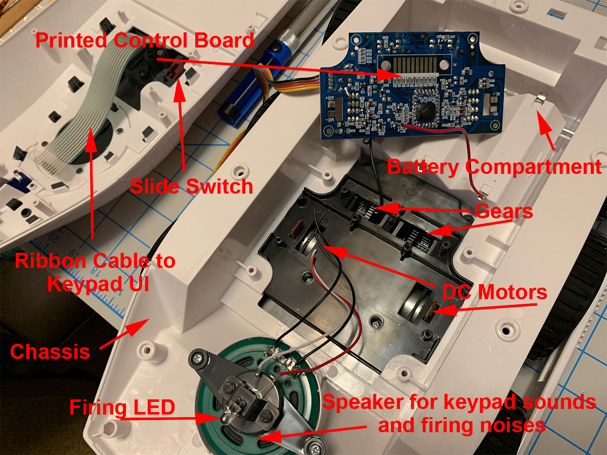
The Inter-workings
I was able to get an understanding of how the PCB was wired to the DC motor and how it powered the wheels as well as understanding how light and sound effects were wired up as well.
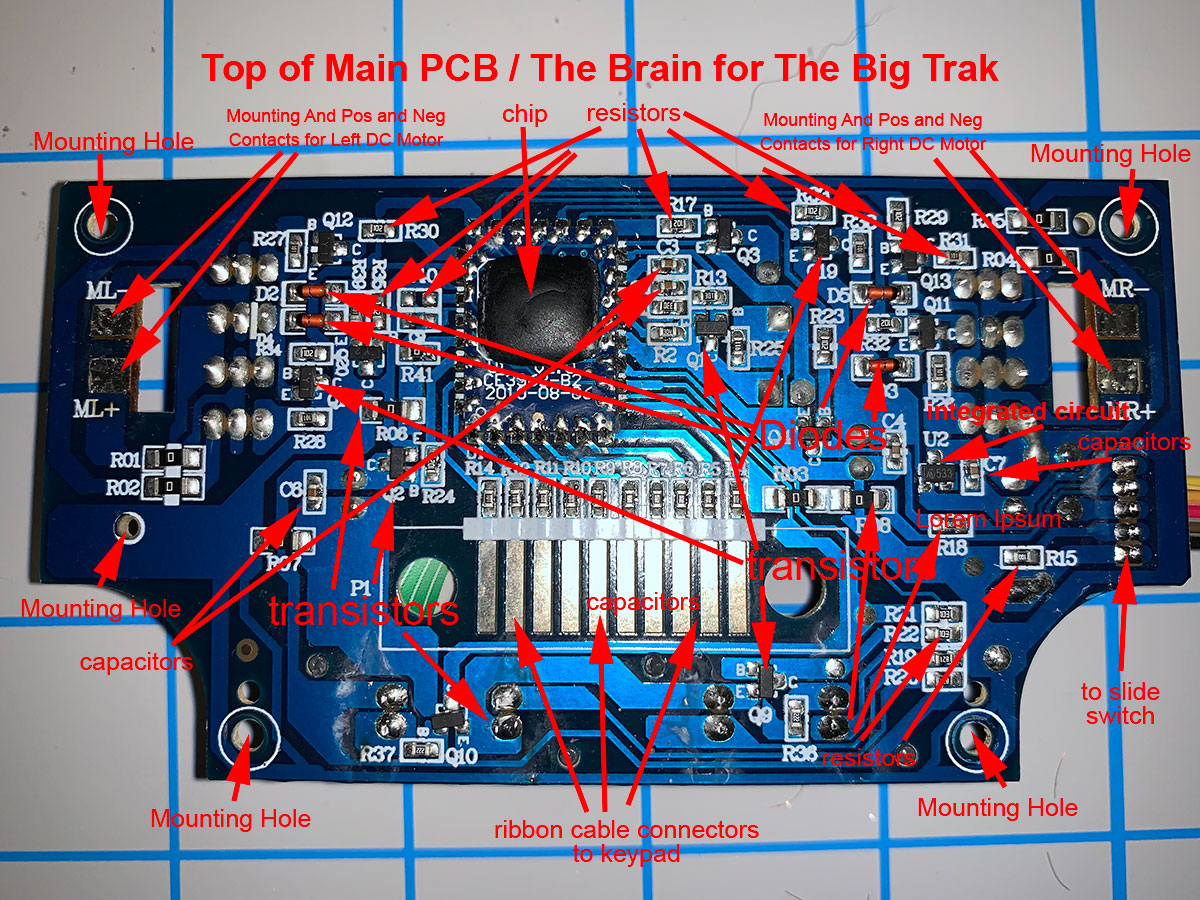
The Old Brain.
Here is a close-up of the PCB and the main processing chip (black square). This is what processes the command from the interface to the wheels, light and speaker.
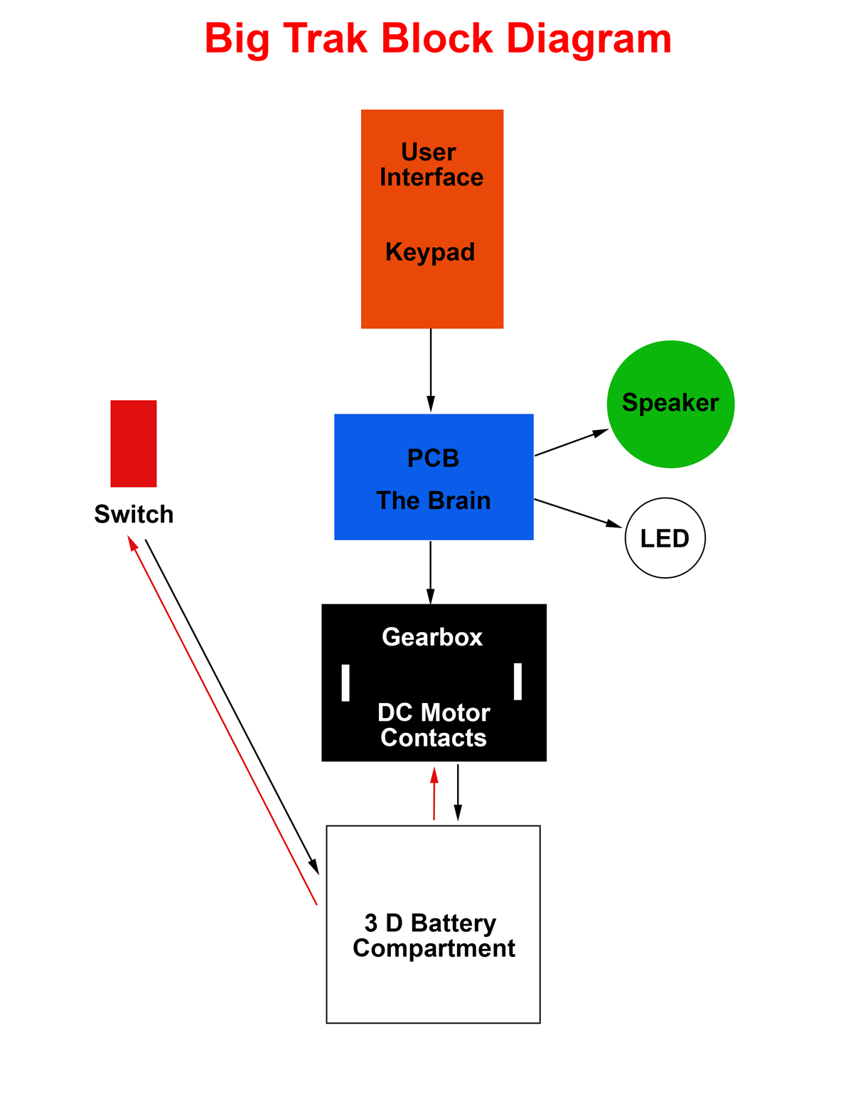
Breaking Down Existing Interactive Features.
This is a schematic of how everything comes together to work and power the Big Trak.
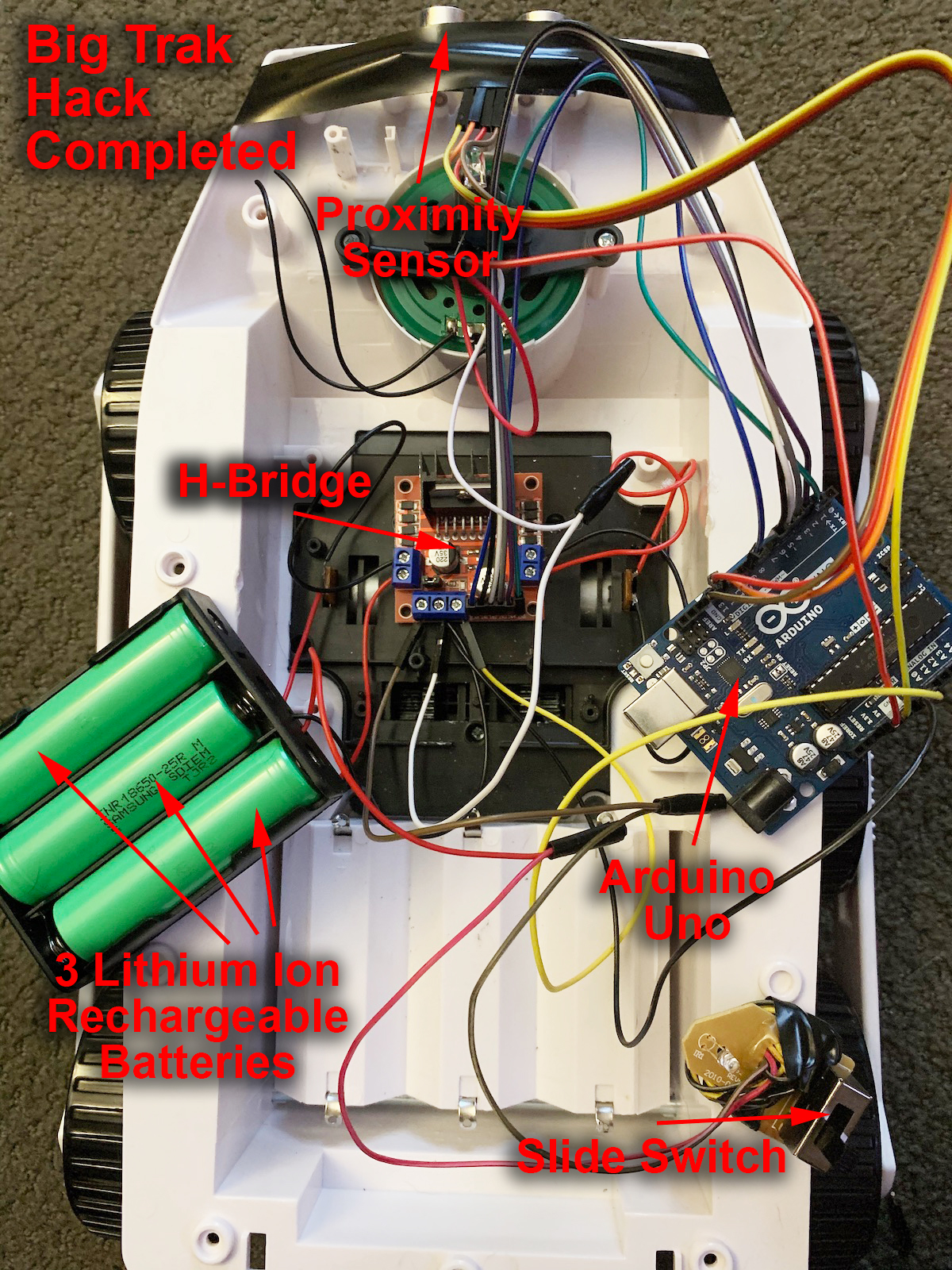
Introducing the New Functionality.
Now I replaced the PCB with the Arduino Board and added a Proximity Sensor in the front of the Big Trak. Also I replaced the D battery powered source with a much more efficient rechargeable set of 3 lithium ion batteries.
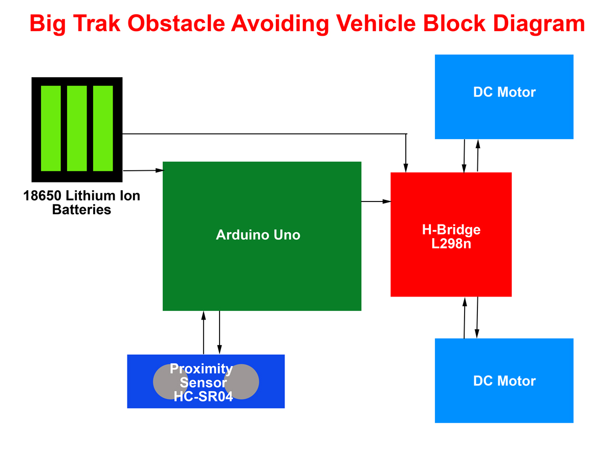
Breakdown of the New Functionality.
This is a schematic of how the new Arduino processor powers an H bridge which then powers the DC motor. Also the Proximity Sensor is seen here - hardwired to the Arduino board.
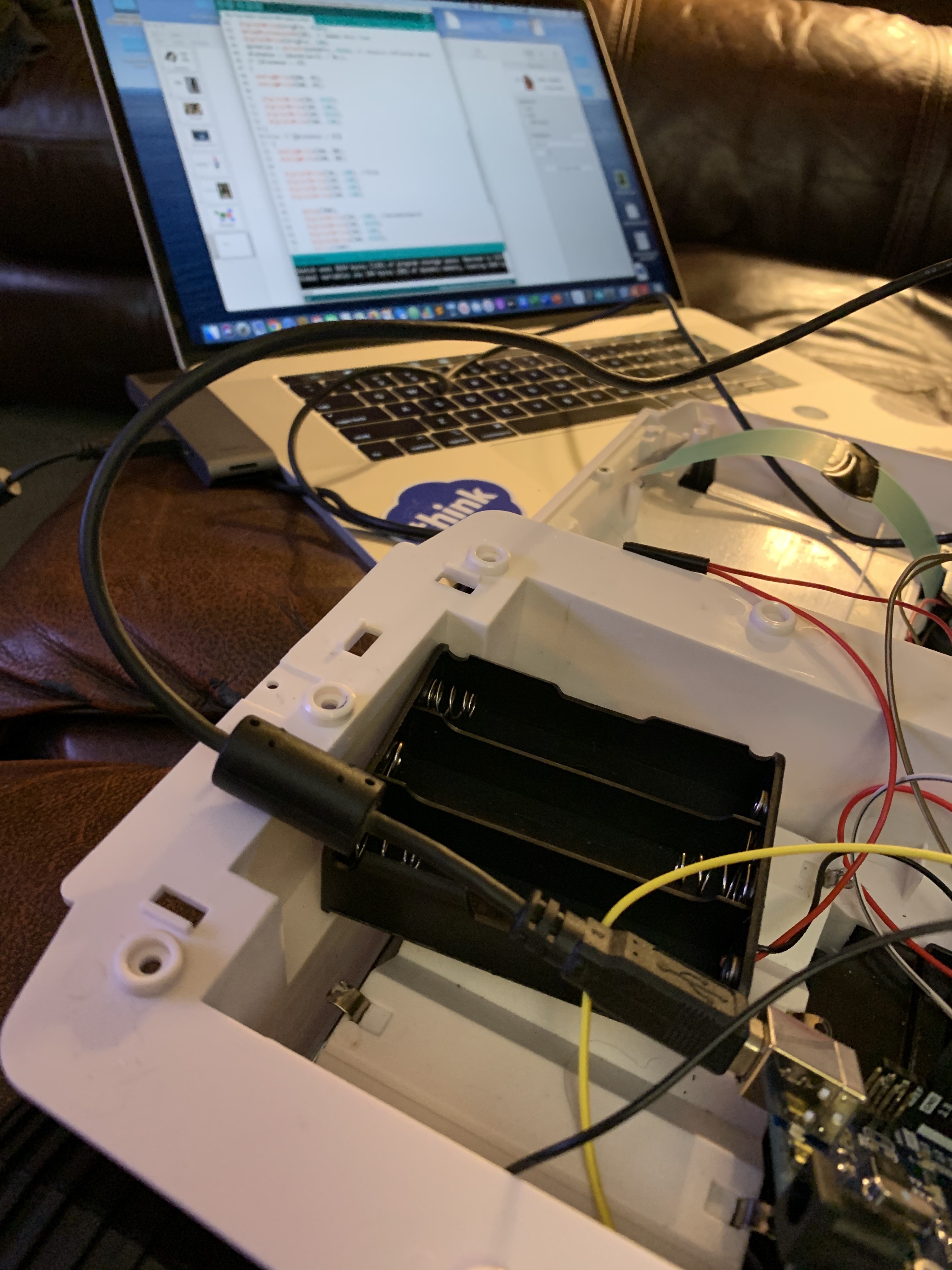
Hand-code & Flash the Arduino
Here we can see a good amount of code that is required to get the Arduino to execute the new commands based on its new brain and built in sensor. This code is uploaded directly from the computer to the Arduino board.
Code:
int trigPin = 12; // trig pin of HC-SR04
int echoPin = 13; // Echo pin of HC-SR04
const int IN1 = 6;
const int IN2 = 7;
const int IN3 = 4;
const int IN4 = 5;
const int ENA = 9;
const int ENB = 3;
long duration, distance;
void setup() {
delay(2000);
Serial.begin(9600);
pinMode(trigPin, OUTPUT);
pinMode(echoPin, INPUT);
pinMode (IN1, OUTPUT);
pinMode (IN2, OUTPUT);
pinMode (IN3, OUTPUT);
pinMode (IN4, OUTPUT);
pinMode (ENA, OUTPUT); // Pulse Width Modulation allow to control of speed
pinMode (ENB, OUTPUT); // Pulse Width Modulation allow to control of speed
// Turn off motors - Initial state
digitalWrite(IN1, LOW);
digitalWrite(IN2, LOW);
digitalWrite(IN3, LOW);
digitalWrite(IN4, LOW);
}
void loop() {
float duration, distance;
v
digitalWrite(trigPin, LOW);
delayMicroseconds(2);
digitalWrite(trigPin, HIGH);
delayMicroseconds(10);
digitalWrite(trigPin, LOW);
duration = pulseIn(echoPin, HIGH); // receive reflected waves
distance = (duration/2) / 29.1; // Convert to centimeters
if (distance > 20)
{
analogWrite(ENA, 45); //Control speed when moving forward
analogWrite(ENB, 45);
digitalWrite(IN1, HIGH); // Proceed forward
digitalWrite(IN2, LOW);
digitalWrite(IN3, HIGH);
digitalWrite(IN4, LOW);
}
else if (distance < 21)
{
analogWrite(ENA, 60); //Control speed in reverse
analogWrite(ENB, 60);
digitalWrite(IN1, LOW); //Stop
digitalWrite(IN2, LOW);
digitalWrite(IN3, LOW);
digitalWrite(IN4, LOW);
delay(350);
digitalWrite(IN1, LOW); //Move backward
digitalWrite(IN2, HIGH);
digitalWrite(IN3, LOW);
digitalWrite(IN4, HIGH);
delay(1500);
digitalWrite(IN1, LOW); //Stop
digitalWrite(IN2, LOW);
digitalWrite(IN3, LOW);
digitalWrite(IN4, LOW);
delay(1500);
digitalWrite(IN1, HIGH); //turn slightly
digitalWrite(IN2, LOW);
digitalWrite(IN3, LOW);
digitalWrite(IN4, LOW);
delay(350);
}
}